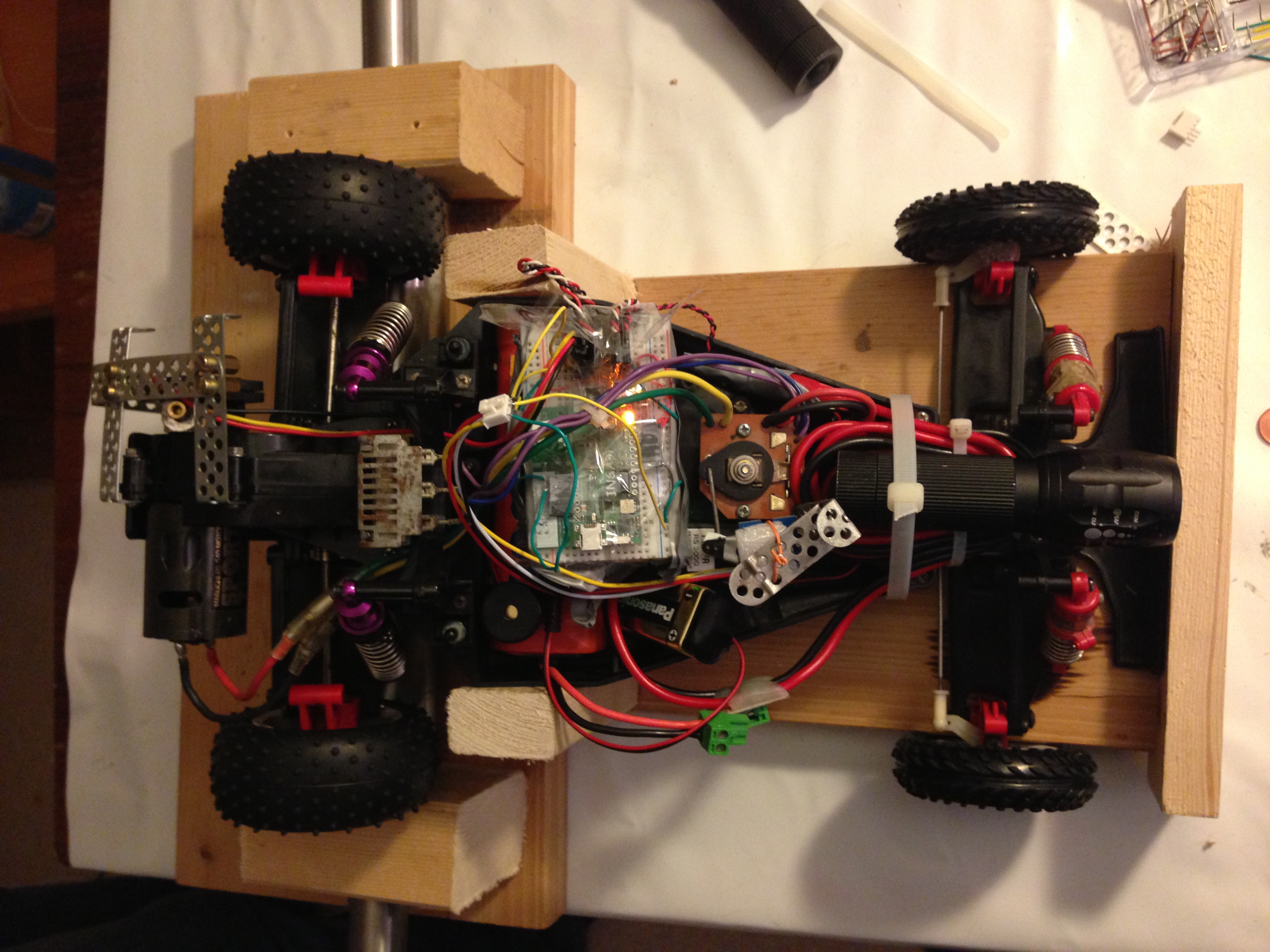
Over christmas, my brother and me were bored and were looking for something exciting to do. He has been playing with Arduino for quite a while and I am working with INGA in my day job. Since INGA is based on AVR microcontrollers, I had the vision to make it to work using the Arduino software for quite some time. Furthermore, we have a Tamiya Bear Hawk remote controllable car lying around that we did not use for some years. In fact, it is a quite old RC model but has a powerful Mabuchi RS-540 motor. Furthermore, the car features a mechanical speed controller (MSC) and is quite light weight which makes it almost impossible to drive safely but produces lots of fun. So, it is an ideal starting point for optimizations. I know, that a couple of guys have done similar things. However, I was unable to find a clear statement of what they did and what the problems were including their source code. Therefore, I have typed up our own way of doing it. The biggest problem that we encountered was the absence of a soldering iron. This lead to a bunch of electrical contact problems that we could have avoided by simply soldering. We tried to avoid them by applying lots of tape to our breadboard but this only worked temporarily. Therefore, please do solder things to make them reliable.
Porting Arduino to INGA
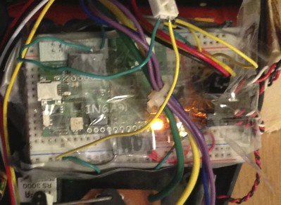
Porting over the Arduino software to INGA has been quite simple. To support the board, I had to modify the board specific config of Arduino. Next up, I have merged several sensor driver libraries into the repository, to support the gyroscope, the accelerometer and the air pressure sensor of INGA. Supporting the Atmel AT86RF231 IEEE 802.15.4 radio was reasonably easy since we could use the existing Contiki driver for the radio. The code can be found in the ArduINGo GIT repository. I have used the same abstractions for pins, etc. that Arduino uses. Please use the INGA schematics with the INGA specific header file in ArduINGo to figure out which pin number goes to which hardware port on the actual circuit board.

In the Figure you see the original name of the Pin from the INGA schematics. Furthermore, I have listed the number of the Pin in Arduino speech (P 16 is pin number 16). However, there are a couple of Pins that have multiple uses:
- MSPI[0-2] are used for the MSPI Bus connecting the accelerometer, the flash and and the SD card. If you want to use one of these components, do not interfere with those pins.
- SCA / SCL is for I2C and connects the gyroscope and the air pressure sensor. If you want to use any of those, do not tamper with those pins.
- RX / TX are the RS232 lines that are connected to the FTDI USB/serial converter chip. Since INGA is flashed over serial, better do not do anything with those pins.
- Pins 18 – 21 are used for JTAG programming. You can use them, but as far as I know, you will have to disable JTAG beforehand.
Driving the car with ArduINGo
Driving an RC car requires 4 things:
- A Controller that the operator (the driver) can use to issue commands
- Wireless transmission of the commands
- Component to interpret the commands and convert them into steering and throttle
- A chassis with suspension and a motor
The last element was fixed since we had the car already. I will outline the remaining three elements in the following sections.
How to control the car using INGA?
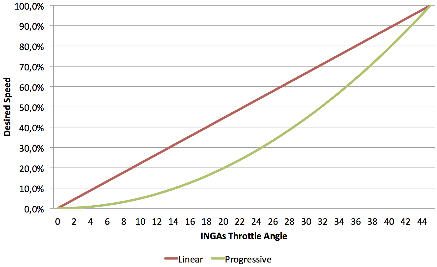
Our stock remote control uses two sticks – one for throttle and one for steering. The stick for steering defaults to the “straight forward” position and allows the driver to steer left and right. The throttle stick defaults to “no throttle” and allows to go forward and backward. The car does not have a brake. Braking the car is done by pulling the throttle-stick into the backward section. While is a common concept, it is not very intuitive. Furthermore, having sticks on the Arduino is simple from an electronics point of view but packaging them is a problem. Therefore, we were looking for alternative concepts. Similar to the Wii controllers, we decided that picking up the angle of INGA using the built-in accelerometers was the most natural approach we could take. By tilting INGA in two angles, the driver can control the throttle position as well as the steering commands. We also found, that giving a “backward” command to brake the car is neither intuitive nor easy to control. Therefore, the throttle axis of INGA can only be used to drive the car forwards. For going backwards, we will use the button on INGA. Pushing the button will make the car go backwards at a defined (and slow) speed that should be easily controllable. After some tries we figured, that a linear correlation between the angle of INGA and the desired speed of the car is not handy. Probably in combination with the mechanical speed controller, the car is almost undrivable at lower speeds. It happens too quickly, that the car accelerates quite fast and braking is not too easy. Therefore, we have implemented a exponential correlation between angle and desired speed. With a power of 2, a nice progressive increase of desired speed as a function of the holding angle can be realized. You can see the comparison in the following figure:
In our experiments we have found that holding INGA with a steady hand is difficult. Therefore, we have implemented a smoothing approach called the Expontentially Weighted Moving Average (EWMA) over both axis. An alpha of 0.75 has proven to provide a good compromise between smooth control and delay. Furthermore, we have limited the active angle of both axis to +-45 degrees for steering and 0 – 45 degrees for the throttle. The primary motivation to do this is that calculating the holding angle proves to be quite unreliable the closer you get to 90 degrees. Furthermore, we have found that missing feedback to the driver will make the driver go over the maximum angle that has any effect. To avoid that the driver reaches 90 degrees too often, we have limited the angle to 45.
Wireless Transmission of the commands
To allow wireless control of the car, the steering commands have to transmitted over the air. INGA has a built-in IEEE 802.15.4 transceiver which is connected to the microcontroller via SPI. We have adapted the existing driver from Contiki OS and ported it into the Arduino environment. With this driver, packets can be transmitted on the MAC level. Since the radio hardware does media access (CSMA/CA), acknowledgements and retransmissions for us, a separate MAC implementation is not necessary. On top of the driver, we have created a very simple abstraction with which you can “stream” values into a packet and send it of to other nodes. It does allow unicast- and broadcast transmissions and involves no further magic. That said, it does not route and multi-hop communication will not work at all. However, for many applications this level of abstraction should be good enough. We have normalized the steering commands to values between 0 and 10000. For the steering, 0 means “100% left”, 5000 means “straight foward” and 10000 means “100% right”. For the throttle, the same concept applies: 0 means “100% backward”, 5000 means “no power” and 10000 means “100% forward”. We sample the accelerometer with approximately 100 Hz and send of the two normalized values (16 bit each) in a unicast radio frame towards the receiver. To avoid interference by other active IEEE 802.15.4 nodes, we have a 16 bit magic number in front of each packet. The receiver constantly listens for packets. If a packet with the magic number arrives, the contained data is fetched and fed into the servo controller to make the steering commands happen. The update frequency is dictated by the sender. We have implemented a delay of 10 ms between two samples, so that the packet frequency should be somewhere below 100 Hz.
Interpreting steering commands on the car
Now that we have the normalized steering commands on the car, we have to convert them into something to make the car move and change direction. On the particular car that we have, the steering is controlled by a servo. Servos (in general?) have a 3-pin connector with Vcc, GND and PWM whereas the last pin contains a pulse-width modulated signal that tells the servo into which direction to move. Arduino contains abstraction for Servo control that only need the pin to which the servo is connected and the angle to which the servo has to turn. We have calibrated the zero position of the servo and mapped the steering commands coming from the sender linearly onto the steering servo. The wiring is quite simple: we have connected the servo to Vcc and GND coming from the cars battery and connected PWM and GND to the appropriate pins of INGA. This simple setup allows to control the servo from software.
For the mechanical speed controller, things are not so simple. This controller consists of a standard servo and a resistor that is controlled by the servo. This means, that movement of the servo is converted into different resistance values which in turn convert to different turning speeds of the motor. Furthermore, the MSC allows the motor (and car) to go forwards and backwards while the direction is also controlled by the servo. Unfortunately, controlling the motor with our MSC is not stepless and far from linear. While this seems to be quite normal for RC cars, it is not intuitive for the user and we wanted to overcome this. Furthermore, the actual turning speed of the motor varies with the offered load – in fact, the servo seems to control the current of the motor. With a human in the loop this may be acceptable, but we wanted to improve. The next logical steps to allow a finer-grained control of the motor is to implement a closed-loop controller for the RPM of the motor. This however requires to measure the RPMs of the motor.
RPM Sensor
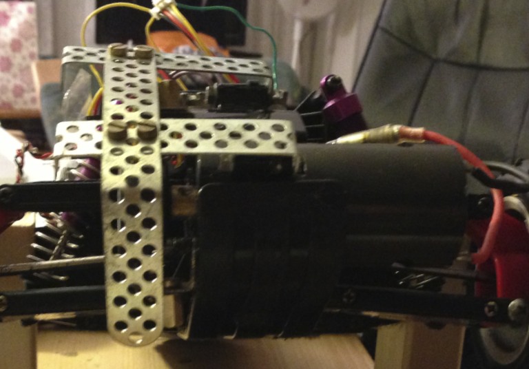
To measure the RPM of the motor, we have thought about different concepts. Since we could not order any parts, we had to modify components that we had at hand. It turns out, that the Seeedstudio Flowmeter is based on a magnet and a hall sensor. We have taken the sensor apart and extract both – the magnet and the hall sensor. We have glued the magnet onto the shaft of the motor and mounted the sensor on the oposite side of the motor. This allows the magnet to turn freely inside the sensor with the sensor picking up 3 ticks for round of the motor.

The sensor is connected to Vcc and GND of the car and the a digital input pin and GND of INGA. We have configured the input pin to be an interrupt and count all incoming ticks in 100 ms. We divide the number of ticks by 3 and divide by the time constant to calculate the number of rounds per minute (RPM) that the motor is currently producing. This allows us to implemented a closed-loop controller that adapts the motor RPM to the desired RPM of the user. However, the hall sensor only provides information about the RPM but not about the direction the motor is currently turning. Since the inertia is small, the motor may change turning directions quickly and figuring the direction out in software is problematic. Therefore, we need another sensor for this purpose.
Direction Sensor
To find out the direction into which the motor is turning at the moment, we would have to have another sensor connected to the shaft of the motor. Unfortunately, we did not have the necessary parts and so we came up with an alternative idea: We assume that the mechanical movement of the servo is slow enough for the motor to change turning direction in time. Therefore, finding out the position of the servo is good enough to figure out the direction of the motor.
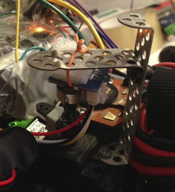
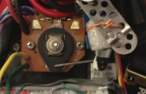
We have used a potentiometer and glued it onto the servo controlling the mechanical speed controller. We have connected Vcc and GND to INGAs power supply and have connected signal to one of the analog inputs of INGA. This allows us to sample the voltage coming from the potentiometer. Since we only need to know the direction into which the motor is currently turning, we only have to compare the current value with the zero value. We calibrate the zero position during each startup of our program on the car to compensate for changing voltages, etc. On retrospective, finding out the motor direction may also be possible in pure software. Our first approach was to detect zero-crossings on actual motor RPMs and then change a direction status variable. However, this heuristic turned out to be ineffective and error prone and tended to confuse our controller (see next section). However, looking at a sufficiently large moving average of the servo position compared to the current value may enable us to reliably detect the current turning direction. Up until now, we did not explore this path.
PID RPM Controller
With the two sensors, we have a good idea of the current RPMs of the motor. Furthermore, the servo attached to the mechanical speed controller allows us to control the motor. The next task for us was to implement a PID closed-loop controller to accurately control the motor RPMs. Initially, we have experimented with a simple P controller but found that it cannot control the system good enough for our goals. To find the necessary values for the controller, we need a couple of test runs of the car. To do those in a controlled environment, we have created a dynamometer (dyno) as outlined in the next section. On the dyno, we have tried out how the reaction of the car towards throttle commands “feels”. While this is a highly subjective metric, we think that this is a viable approach to our problem. Driving the car should feel right afterwards. Our main priorities while finding the right values for the controller were as follows:
- Powerful acceleration and quick response to throttle commands
- Active breaking of the current RPM is above the target RPM
- Smoothness
After a series of tests, we came up with the following values:
- Kp = 2.2
- Ki = 100
- Kd = 1
We have further found, that the car is not breaking hard enough when the driver reduces power. Therefore, we have implemented a variable Kp. Under breaking (current RPM > target RPM) we change Kp to 5 * Kp.
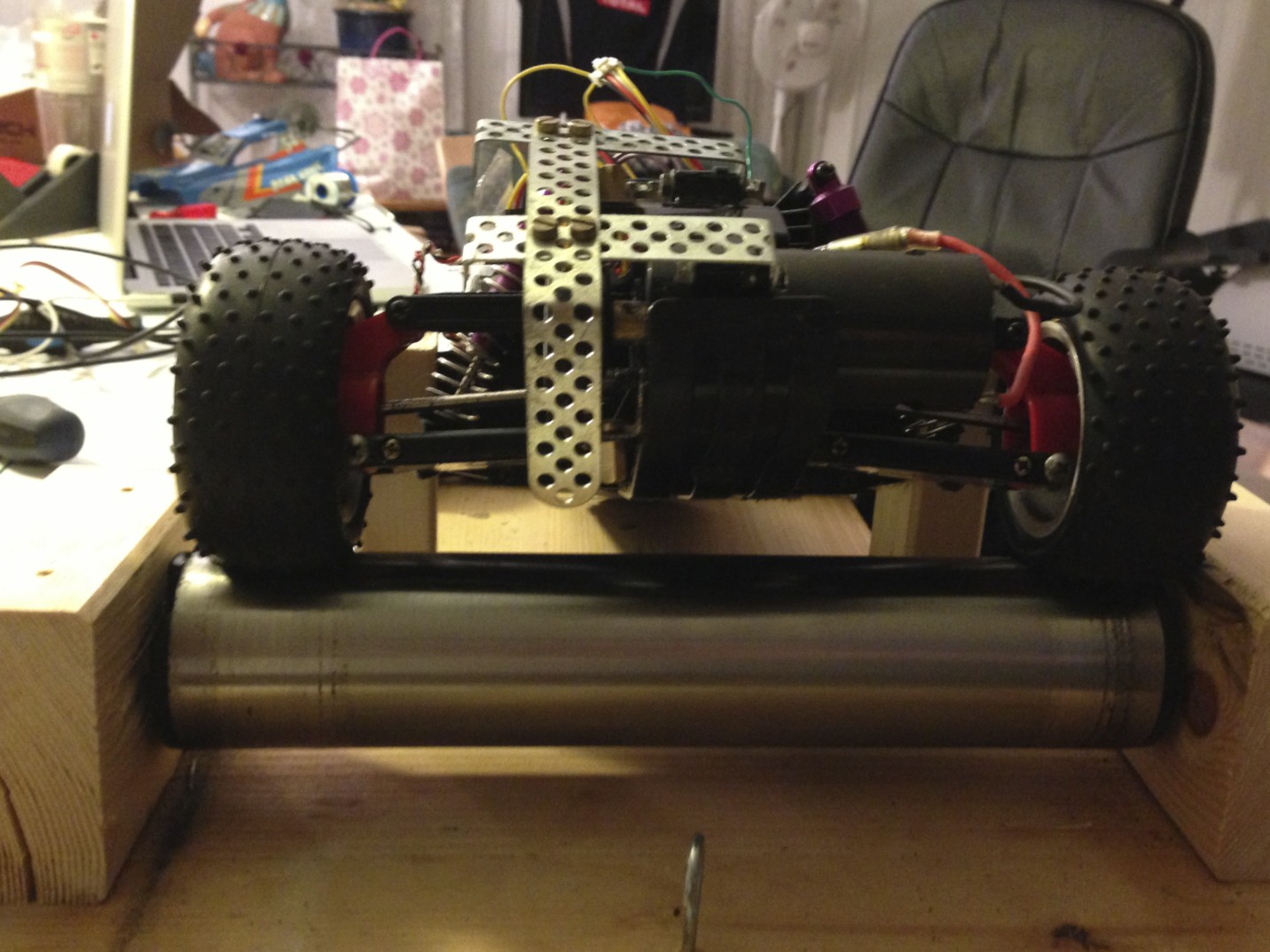
Rolling Pin – Dynamometer
As said in the previos section, we needed a test setup that allows to test the controller settings in the lab. Furthermore, we needed more or less reproducible conditions to see if changes did what they were intended to do. We have used a standard kitchen rolling pin (that thing that you use to make your pizza dough flat) mounted between two wooden blocks. We have furthermore mounted the car in a way, that does not allow the car to move.
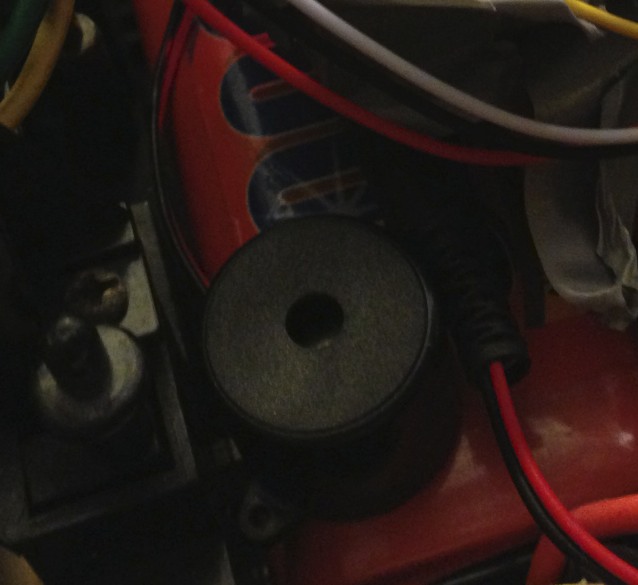
Beep on Reverse
As we all know, vehicles driving backwards are extremely dangerous. 😉 This is why trucks have the beep noise when reversing. To imitate this behavior, we have integrated a beeper into our car. We have connected a transistor to a digital output pin of our car and use it to control the beeper. Based on video footage found on youtube, we have configured the beeper to be 500ms on and 400ms off. This seems to be a good approximation of the beeper found in commercial trucks. We enable the beeper once the input to the car indicates to go backwards.
Safety procedures – Radio timeout
With the old (analog?) remote control it happened from time to time, that the car drove out of range or that the transmitter or receiver would stop working. This is a bad thing, since the servos will remain in their position until they get further instructions. In other words: forever.
This is especially problematic, because when the cars speeds away from you and you loose contact, it will continue to do so until the batteries are drained or until it finds an obstacle to crash into. Both not very desirable.
Therefore, we have implemented a timeout mechanism into the car. When no valid steering packets have been received within 100 ms, the steering will be put into the initial “straight forward” position. The desired RPM for the PID controller is set to 0, so that the car automatically breaks until it stands still.
We have tested the behavior multiple times by simply switching of the sender and it turned out to be extremely helpful. It also acts as our emergency shutdown. When something goes wrong, we switch off the car and it comes to a full stop as quickly as possible.
Result
The result of our effort is actually quite impressive. The car drives like hell (just like before) but has a whole different steering concept and the throttle is much easier to controller. Unfortunately, we found a premature end because a port of the front suspension broke and we did not have replacement parts. You can see a video in youtube. Unfortunately, the commentary is in german – but the essential things are visible without understanding a word.
Future Work
After we have mechanically repaired the car, we still have a number of steps to go. Most importantly, we will replace the mechanical speed controller for an electronic version. The interface is the same, but it will make controlling the motor much easier. Furthermore we will replace our breadboard with a hole matrix board with proper connectors for INGA and the other external components. Alternatively, we may produce an adapter board which enables us to use INGA with standard Arduino shields. Also, the parameters for the PID controller will need to be adapted to the new speed controller and to enable even faster breaking and acceleration. Finally, we plan to implement driving aids based on INGAs gyroscope and accelerometer. With these two sensors, we should be able to limit the motor power of the desired and the achieved turning angle mismatch and do other fun things.
Code
Remote Control
#include
#include
#include
#include

/* Debugging makes things slow */
#define DEBUG 0

/* adxl setup */
double adxl_alpha_X = 0.75;
double adxl_alpha_Y = 0.75;
int adxl_min_degree_X = -50;
int adxl_max_degree_X = 0;
int adxl_min_degree_Y = -45;
int adxl_max_degree_Y = 45;

/* adxl init */
ADXL345 adxl;
double adxl_dX_ewma;
double adxl_dY_ewma;

/* state init */
int state_steering;
int state_power;

/* button setup */
int button_pin = BUTTON;

/* input config */
int input_zero = 5000;
int input_range = 5000;

/* mapping config */
float mapping_power = 2;

/* LED config */
int led_radio = LED_GREEN;

// #######################################################

#define PI (4*atan(1))

double rad2deg(double rad)
{
      return (180.0 * rad / (PI));
}

// #######################################################

void mapping_setup()
{
}

void mapping_loop()
{
}

int mapping_map_power(int power)
{
  /* Calculate what the user actually wants */
  return ((pow(power, mapping_power) * ((float) input_range)) / (pow(abs(adxl_min_degree_X), mapping_power))) + ((float) input_zero);
}

int mapping_map_steering(int steering)
{
  return map(steering, adxl_min_degree_Y, adxl_max_degree_Y, 0, 10000);
}

// #######################################################

void state_setup()
{
}

void state_loop()
{
  state_update();
}

void state_set_power(int power)
{
  state_power = power;
}

void state_set_steering(int steering)
{
  state_steering = steering;
}

void state_update()
{
  radio_send(state_steering, state_power);
}

// #######################################################

void adxl_setup()
{
  adxl.begin();
}

void adxl_loop()
{
  double aX;
  double aY;
  double dX;
  double dY;

  /* Read the accelerometer */
  adxl.read();

#if DEBUG
  Serial.print("ADXL: X ");
  Serial.print(adxl.g.x, DEC);
  Serial.print(", Y ");
  Serial.print(adxl.g.y, DEC);
  Serial.print(", Z ");
  Serial.println(adxl.g.z, DEC);
#endif

  /* Readings in reliable angles only */
  if( adxl.g.z < 10 && adxl.g.z > -10 ) {
    return;
  }

  /* Ignore when the node is upside down */
  if( adxl.g.z > 0 ) {
    return;
  }

  /* Calculate the X and Y angles */
  aX = atan( ((double) adxl.g.x) / ((double) adxl.g.z) );
  aY = atan( ((double) adxl.g.y) / ((double) adxl.g.z) );

  /* Convert the values into degrees */
  dX = rad2deg(aX);
  dY = rad2deg(aY);

  /* Cap at the maximum value */
  if( dX > adxl_max_degree_X ) {
    dX = adxl_max_degree_X;
  } else if( dX < adxl_min_degree_X ) {
    dX = adxl_min_degree_X;
  }

  /* Cap at the maximum value */
  if( dY > adxl_max_degree_Y ) {
    dY = adxl_max_degree_Y;
  } else if( dY < adxl_min_degree_Y ) {
    dY = adxl_min_degree_Y;
  }

  /* Smooth the X axis */
  if( adxl_dX_ewma == 0 ) {
    adxl_dX_ewma = dX;
  } else {
    adxl_dX_ewma = adxl_alpha_X * dX + (1-adxl_alpha_X) * adxl_dX_ewma;
  }

  /* Smooth the Y axis */
  if( adxl_dY_ewma == 0 ) {
    adxl_dY_ewma = dY;
  } else {
    adxl_dY_ewma = adxl_alpha_Y * dY + (1-adxl_alpha_Y) * adxl_dY_ewma;
  }

#if DEBUG
  Serial.print("ANGLE: X ");
  Serial.print(dX, DEC);
  Serial.print(" ");
  Serial.print(adxl_dX_ewma, DEC);
  Serial.print(", Y ");
  Serial.print(dY, DEC);
  Serial.print(" ");
  Serial.println(adxl_dY_ewma, DEC);
#endif

  /* Only update the power, when the button is not pressed - otherwise we reverse */
  if( !button_pressed() ) {
    state_set_power(mapping_map_power(-adxl_dX_ewma));
  }

  /* Update the steering */
  state_set_steering(mapping_map_steering(-adxl_dY_ewma));
}

// #######################################################

void radio_setup()
{
  Radio.begin(15);
}

void radio_loop()
{
  Radio.periodic();
}

void radio_send(int steering, int power)
{
  int steering_normalized;
  int power_normalized;
  int magic;

  /* Set our magic byte */
  magic = 0x99;

#if DEBUG
  Serial.print("Sending ");
  Serial.print(steering, DEC);
  Serial.print(" and ");
  Serial.println(power, DEC);
#endif

  /* Put all values in a paket */
  Radio.write(magic);
  Radio.write(steering);
  Radio.write(power);

  /* Send the packet off */
  Radio.sendMessage(17);

  /* Toggle the LED */
  if( digitalRead(led_radio) ) {
    digitalWrite(led_radio, LOW);
  } else {
    digitalWrite(led_radio, HIGH);
  }
}

// #######################################################

void button_setup()
{
  /* Set the button PIN as input */
  pinMode(button_pin, INPUT);
}

int button_pressed()
{
  int buttonState;

  /* Read button state */
  buttonState = digitalRead(button_pin);

  /* Invert Readings */
  if( buttonState == 1 ) {
    return 0;
  } else {
    return 1;
  }
}

void button_loop()
{
  /* if the button is pressed, reverse */
  if( button_pressed() ) {
    /* Reverse with 20% of the maximum */
    state_set_power(input_zero - 0.1 * input_range);
  }
}

// #######################################################

void led_setup()
{
  pinMode(led_radio, OUTPUT);
}

void led_loop()
{
}

// #######################################################

// the setup routine runs once when you press reset:
void setup() {
  Serial.begin(9600);

  // initialize the digital pin as an output.
  Serial.println("INIT LED");
  led_setup();

  Serial.println("INIT Button");
  button_setup();

  Serial.println("INIT ADXL");
  adxl_setup();

  Serial.println("INIT radio");
  radio_setup();

  Serial.println("INIT Mapping");
  mapping_setup();

  Serial.println("INIT done");
}

// the loop routine runs over and over again forever:
void loop() {
  button_loop();
  adxl_loop();
  radio_loop();
  state_loop();
  mapping_loop();
  led_loop();

  /* Run at 100 Hz */
  delay(10);
}
On the Car
#include
#include
#include

/* Enabling debugging makes the controller go mad! */
#define DEBUG 0

/* servo config */
int servo_steering_pin = 16;
int servo_steering_zero = 80;
int servo_steering_range = 35;
int servo_power_pin = 17;
int servo_power_zero = 92;
int servo_power_range = 50;

/* servo init */
Servo servo_power;
Servo servo_steering;
int servo_power_direction;

/* radio init */
int radio_packet_counter = 0;
unsigned long radio_last_update = 0;
unsigned long radio_timeout = 100;

/* rpm config */
int rpm_ticks_per_round = 3;
int rpm_hallsensor_pin = 10;
int rpm_hallsensor_irq = 0;

/* rpm init */
volatile int rpm_rounds;
unsigned long rpm_last_time = millis();
int rpm_measurement_period  = 100;
float rpm_current;

/* ctrl config */
int ctrl_max = 19000;
float ctrl_p = 2.2;
float ctrl_p_multiplier = 5.0;
float ctrl_i = 100;
float ctrl_d = 1;

/* ctrl init */
int ctrl_target_power;
int ctrl_current;
int ctrl_rpm_current;
long ctrl_i_current;
float ctrl_d_current;
long ctrl_difference_current;

/* input config */
int input_zero = 5000;
int input_range = 5000;

/* reverse config */
int reverse_pin = 24;
int reverse_time_on  = 500;
int reverse_time_off = 400;

/* reverse init */
int reverse_status;
int reverse_pin_status;
unsigned long reverse_last_time = millis();
int reverse_changed;

/* adc config */
int adc_pin = A1;
int adc_zero = 386;

/* LED config */
int led_radio = LED_GREEN;
int led_rpm = LED_RED;

// #######################################################

void adc_setup()
{
  /* Configure the pin as INPUT */
  pinMode(adc_pin, INPUT);

  /* And take the initial value as zero */
  adc_zero = analogRead(adc_pin);

#if DEBUG
  Serial.print("ADC Zero is ");
  Serial.println(adc_zero, DEC);
#endif
}

void adc_loop()
{
  int sensorValue;

  /* Read the analog value */
  sensorValue = analogRead(adc_pin);

  /* Compare to the reference */
  if( sensorValue > adc_zero ) {
    servo_power_direction = +1;
  } else {
    servo_power_direction = -1;
  }
}

// #######################################################

void reverse_setup()
{
  /* Switch pin to output */
  pinMode(reverse_pin, OUTPUT);

  /* Disable by default */
  reverse_status = 0;
  reverse_last_time = 0;
  reverse_pin_status = 0;
  digitalWrite(reverse_pin, LOW);
}

void reverse_loop()
{
  if( reverse_status == 0 ) {
    reverse_pin_status = 0;
    reverse_update();
    return;
  }

  if( (reverse_pin_status == 1) && (millis() - reverse_last_time) > reverse_time_on ) {
    reverse_pin_status = 0;
    reverse_last_time = millis();
    reverse_update();
  } else if( (reverse_pin_status == 0) && (millis() - reverse_last_time) > reverse_time_off ) {
    reverse_pin_status = 1;
    reverse_last_time = millis();
    reverse_update();
  }
}

void reverse_update()
{
  if( reverse_pin_status == 1 ) {
    digitalWrite(reverse_pin, HIGH);
  } else {
    digitalWrite(reverse_pin, LOW);
  }
}

void reverse_on()
{
  if( !reverse_status ) {
    reverse_pin_status = 1;
    reverse_update();
  }

  reverse_status = 1;
  reverse_update();
}

void reverse_off()
{
  if( reverse_status ) {
    reverse_pin_status = 0;
    reverse_update();
  }

  reverse_status = 0;
  reverse_update();
}

// #######################################################

void serial_setup()
{
  Serial.begin(9600);
  Serial.println("INIT");
}

void serial_loop()
{
}

// #######################################################

void servo_setup()
{
  /* Attach the servo library to our two output pins */
  servo_steering.attach(servo_steering_pin);
  servo_power.attach(servo_power_pin);

  /* And put the servos into a defined state */
  servo_steering.write(servo_steering_zero);
  servo_power.write(servo_power_zero);
}

void servo_loop()
{
}

void servo_set(int steering, int power)
{
  servo_set_power(power);
  servo_set_steering(steering);
}

void servo_set_steering(int steering)
{
  /* Map input values onto the values for the servo library */
  int steering_servo = map(steering, input_zero + input_range, input_zero - input_range, servo_steering_zero - servo_steering_range, servo_steering_zero + servo_steering_range);

  /* DEBUG to serial terminal */
#if DEBUG
  Serial.print("Steering ");
  Serial.println(steering_servo);
#endif

  servo_steering.write(steering_servo);
}

void servo_set_power(int power)
{
  /* Map input values onto the values for the servo library */
  int power_servo = map(power, input_zero - input_range, input_zero + input_range, servo_power_zero + servo_power_range, servo_power_zero - servo_power_range);

  /* DEBUG to serial terminal */
#if DEBUG
  Serial.print("Power ");
  Serial.println(power_servo);
#endif

  /* Write values to the servo library */
  servo_power.write(power_servo);
}

// #######################################################

void led_setup()
{
  // initialize the digital pin as an output.
  pinMode(led_radio, OUTPUT);
  pinMode(led_rpm, OUTPUT);
}

void led_loop()
{
}

// #######################################################

void rpm_setup()
{
  /* Attach the IRQ handler to pin PD2 (10 in Arduino speech) */
  pinMode(rpm_hallsensor_pin, INPUT);
  attachInterrupt(rpm_hallsensor_irq, rpm_interrupt, RISING);
}

void rpm_loop()
{
  float Calc;

  /* Regularly check, if our measurement period has elapsed */
  if ((millis()-rpm_last_time) < rpm_measurement_period) {
    return;
  }

  /* Calculate the number of rpm_rounds in the measurement period */
  Calc = ((float) rpm_rounds)/((float) rpm_ticks_per_round);

  /* Convert it to rpm */
  Calc = Calc * (60000 / (millis() - rpm_last_time));
  rpm_rounds = 0;
  rpm_last_time = millis();
  rpm_current = Calc;

  /* Provide the current RPMs to the controller */
  ctrl_input(((int) Calc) * servo_power_direction);

  /* Debug to the serial port */
#if DEBUG
  Serial.print("RPM: ");
  Serial.print(Calc, DEC);
  Serial.println(" rpm");
#endif
}

void rpm_interrupt(void)
{
  /* Toggle the LED on every IRQ*/
  if( digitalRead(led_rpm) ) {
    digitalWrite(led_rpm, LOW);
  } else {
    digitalWrite(led_rpm, HIGH);
  }

  /* Count rpm_rounds per Time interval */
  rpm_rounds ++;
}

// #######################################################

void radio_setup()
{
  /* Initialize radio with node_id 17 */
  Radio.begin(17);

  /* Enable timeout behaviour */
  radio_last_update = millis();
}

void radio_loop()
{
  /* If a servo_timeout occurs, go into a safe state */
  if( (millis() - radio_last_update) >= radio_timeout ) {
    servo_steering.write(servo_steering_zero);
    ctrl_set(input_zero);
  }

  /* Handle period radio tasks */
  Radio.periodic();

  /* If no packet is waiting for us, return */
  if( Radio.getBufferLength() == 0 ) {
    return;
  }

  /* Toggle LED every 10 packets */
  if( (radio_packet_counter ++) % 10 == 0 ) {
    if( digitalRead(led_radio) ) {
      digitalWrite(led_radio, LOW);
    } else {
      digitalWrite(led_radio, HIGH);
    }
  }

  /* Read int values from packet */
  int magic = Radio.read_int();
  int steering_value = Radio.read_int();
  int power_value = Radio.read_int();

#if DEBUG
  Serial.print("RADIO: ");
  Serial.print(steering_value, DEC);
  Serial.print(" / ");
  Serial.println(power_value, DEC);
#endif

  /* All packets must have the magic byte in front */
  if( magic != 0x99 ) {
    return;
  }

  /* And memorize when we have done that to detect a servo_timeout */
  radio_last_update = millis();

  /* Tell the controller that we have new targets */
  servo_set_steering(steering_value);
  ctrl_set(power_value);

  /* Memorize time for the timeout */
  radio_last_update = millis();
}

// #######################################################

void ctrl_setup()
{
  ctrl_target_power = 0;
  ctrl_difference_current = 0;
}

void ctrl_loop()
{
}

void ctrl_input(int rounds)
{
#if DEBUG
  Serial.print("CTRL: Rounds ");
  Serial.println(rounds, DEC);
#endif

  ctrl_rpm_current = rounds;
  ctrl_update();
}

void ctrl_set(int power)
{
  if( power < input_zero ) {
    reverse_on();
  } else {
    reverse_off();
  }

#if DEBUG
  Serial.print("CTRL: Target ");
  Serial.println(power, DEC);
#endif

  /* Map the input value onto actual RPM */
  ctrl_target_power = map(power, input_zero - input_range, input_zero + input_range, -ctrl_max, ctrl_max);

#if DEBUG
  Serial.print("CTRL: Target mapped ");
  Serial.println(ctrl_target_power, DEC);
#endif
}

void ctrl_update(void)
{
  long target;
  long difference;
  int servo;
  float local_ctrl_p;

  /* Calculate our current difference */
  difference = ((long) ctrl_target_power) - ((float) ctrl_rpm_current);

  /* Copy the ctrl_p */
  local_ctrl_p = ctrl_p;

  /* Adapt P value if we want to brake */
  if( difference < 0 ) {
    local_ctrl_p *= ctrl_p_multiplier;
  }

  /* Feed values into our I controller */
  ctrl_i_current += difference;

  /* Feed values into our P controller */
  ctrl_d_current = ((float) (difference - ctrl_difference_current)) / 100;
  ctrl_difference_current = difference;

  /* Calculate our next target */
  long i_term = ((float) ctrl_i_current) / (((float) ctrl_i) * 100);
  float d_term = ctrl_d * ctrl_d_current;
  target = (long) (local_ctrl_p * ( ((float) difference) + ((float) i_term)  + d_term ));

  /* Cap it to maximum power */
  if( target > ctrl_max ) {
    target = ctrl_max;
  } else if( target < -ctrl_max ) {
    target = -ctrl_max;
  }

  /* DEBUG to Serial */
#if DEBUG
  Serial.print("CTRL: Target ");
  Serial.print(ctrl_target_power, DEC);
  Serial.print(", Current ");
  Serial.print(ctrl_rpm_current, DEC);
  Serial.print(", Now ");
  Serial.print(target, DEC);
  Serial.print(" | i ");
  Serial.print(i_term, DEC);
  Serial.print(" d ");
  Serial.println(d_term, DEC);
#endif

  /* Map it onto the range of the servo */
  servo = map(target, -ctrl_max, ctrl_max, input_zero - input_range, input_zero + input_range);

  /* And set the servo */
  servo_set_power(servo);
}

// #######################################################

void setup()
{
  serial_setup();

  Serial.println("INIT Servo");
  servo_setup();

  Serial.println("INIT LED");
  led_setup();

  Serial.println("INIT Radio");
  radio_setup();

  Serial.println("INIT RPM");
  rpm_setup();

  Serial.println("INIT CTRL");
  ctrl_setup();

  Serial.println("INIT Reverse");
  reverse_setup();

  Serial.println("INIT ADC");
  adc_setup();

  Serial.println("INIT done");
}

void loop() {
  serial_loop();
  servo_loop();
  led_loop();
  radio_loop();
  rpm_loop();
  ctrl_loop();
  reverse_loop();
  adc_loop();
}
Pingback: DIY Robot Project – Plan « devstark